apero_shape_ref_spirou
Contents
1. Description
SHORTNAME: SHAPEREF
Shape reference calibration
In PRV measurements, constraining the exact position of orders on the science array, both in the spectral and spatial dimensions, is key as the position of our spectra on this science array encodes the sought-after velocity of the star. The diffraction orders of SPIRou, and nearly all PRV spectrographs, follow curved lines, and the image slicer has a 4-point structure that is not parallel to the pixel grid.
Within the APERO framework, we decided to split the problem into two parts: a reference shape calibration and a nightly shape calibration. For the reference step, we constrain the bulk motion, as defined through an affine transformation and register all frames to a common pixel grid to well below the equivalent of 1 \(ms^{-1}\). We perform the order localization and subsequent steps on a nightly basis as it has the significant advantage that registered frames have all orders at the same position to a very small fraction of a pixel. Furthermore, having registered frames allows for better error handling within APERO; one does not expect pixel-level motions between calibrations after this step.
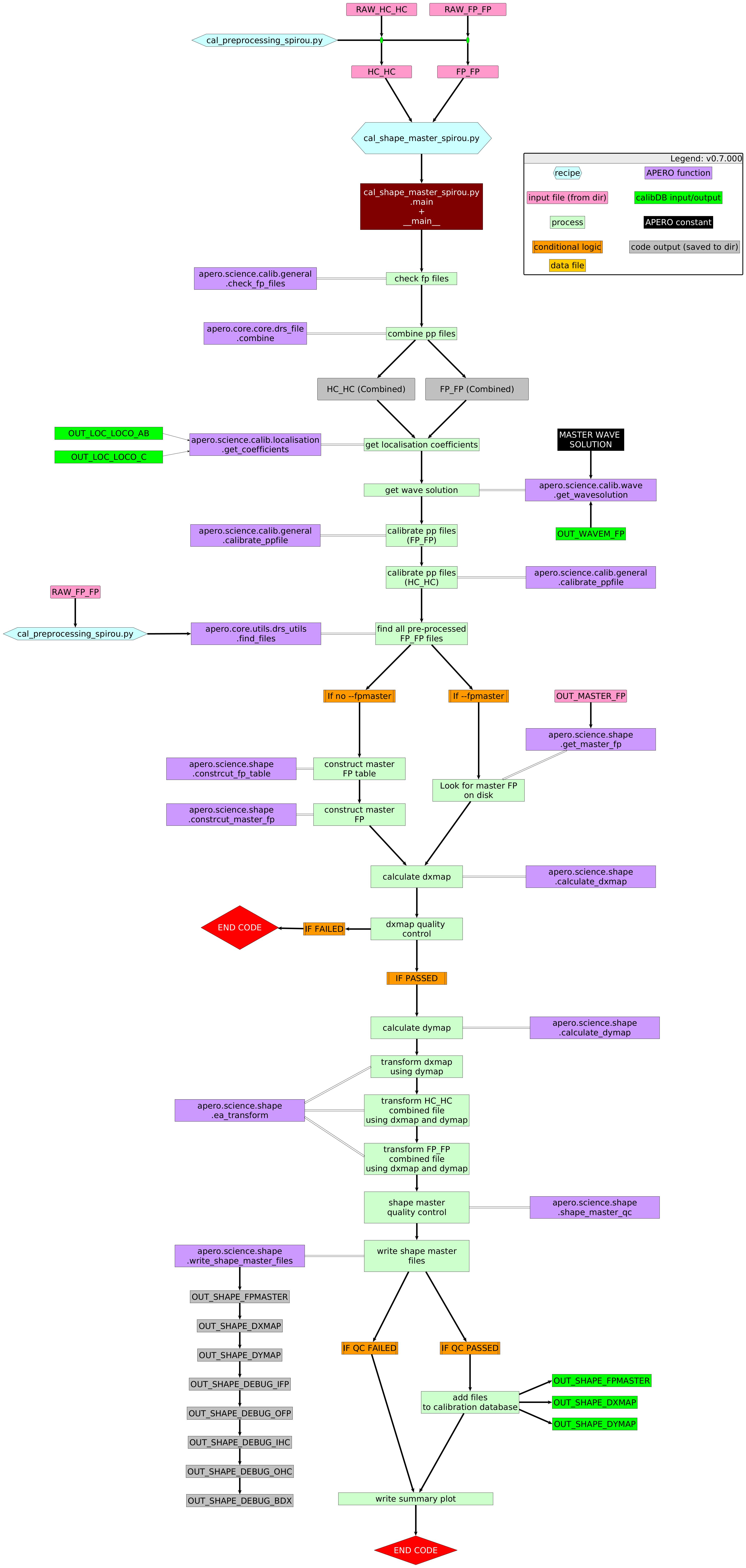
The reference shape recipe takes preprocessed FP_FP and HC_HC files (as many as given by the user or as many as occur on the nights being used via apero_processing). The reference shape recipe combines the FP_FP files into a single FP_FP file and the HC_HC files into a single HC_HC file (via a median combination of the images). After combining, the FP_FP and HC_HC images are calibrated using our standard image calibration technique. In addition to the combined FP_FP and HC_HC, we create a reference FP image. This reference FP image is created by selecting a subset of 100 FP_FP files (uniformly distributed across nights) and combining these with a median. This reference FP image is then saved to the calibration database for use throughout APERO.
The registration through affine transformations is done using the`FP_FP` calibrations. We take the combined FP_FP files and localize in the 2D frame the position of each FP peak and measure the position of the peak maxima. Considering the 3 SPIRou fibers and 4 slices (i.e., 12 2D peaks per FP line), this means there are >100000 peaks on the science array. These are taken as reference positions. For each calibration sequence, we then find the affine transformation that minimizes the RMS between the position of the FP and the FP reference image calibration. The resulting affine transformation consists of a bulk shift in dx, dy, and a \(2\times2\) matrix that encodes rotation, scale, and shear. These values are kept and can be useful to identify shifts in the optics (e.g., after earthquakes or thermal cycles) as well as very slight changes in plate scale and angular position of the array which can be of interest in understanding the impact of engineering work onto the science data products. For example, we can readily measure a \(10^{-5}\) fractional change in the SPIRou plate scale following a maintenance thermal cycle of the instrument; the ratio of the point-to-point RMS to the median of the plate scale value is at the \(1.7\times10^{-7}\) level. The interpolations between pixel grids are done with a 3rd order spline. We note that changes in the FP cavity length arise from a number of reasons such as gas leakage and temperature and will lead to a motion of FP peaks on the array that is not due to a physical motion of the array or optical elements within the cryostat. Considering that typical drifts are at the \(\sim0.3\),m/s/day level, to first order this leads to a typical \(10^{-9}\)/day fractional increase in the plate scale along the dispersion direction. This effectively leads to a minute change in the effective dispersion of the extracted file wavelength solution. As this change is common to both the FP, the HC, and the science data, it is accounted for when computing the wavelength solution and cavity length change.
Once the affine transformation has been applied, images are registered to a common grid (the reference FP image). We then construct a transform that makes the orders straight and corrects for slicer structure in the dispersion direction. This leads to the construction of two maps corresponding to x and y offsets that need to be applied to an image to transform it into a rectified image from which a trace extraction can be performed directly through a 1-D collapse in the direction perpendicular to the dispersion of a rectangular box around the order. The y direction map is computed from the order-localization polynomials. The x direction map is determined by first collapsing the straightened orders of a FP_FP calibration and cross-correlating each of the spectral direction pixel rows to find its offset relative to the collapsed-extracted spectrum. The x and y offsets are then saved to the calibration database for use throughout APERO.
2. Schematic
3. Usage
apero_shape_ref_spirou.py {obs_dir}[STRING] --fpfiles[FILE:FP_FP] --hcfiles[FILE:HCONE_HCONE] {options}
{obs_dir}[STRING] // [STRING] The directory to find the data files in. Most of the time this is organised by nightly observation directory
--fpfiles[FILE:FP_FP] // Current allowed types: FP_FP
--hcfiles[FILE:HCONE_HCONE] // Current allowed types: HC_HC
4. Optional Arguments
--database[True/False] // [BOOLEAN] Whether to add outputs to calibration database
--badpixfile[FILE:BADPIX] // [STRING] Define a custom file to use for bad pixel correction. Checks for an absolute path and then checks 'directory'
--badcorr[True/False] // [BOOLEAN] Whether to correct for the bad pixel file
--backsub[True/False] // [BOOLEAN] Whether to do background subtraction
--combine[True/False] // [BOOLEAN] Whether to combine fits files in file list or to process them separately
--darkfile[FILE:DARKREF] // [STRING] The Dark file to use (CALIBDB=DARKM)
--darkcorr[True/False] // [BOOLEAN] Whether to correct for the dark file
--flipimage[None,x,y,both] // [BOOLEAN] Whether to flip fits image
--fluxunits[ADU/s,e-] // [STRING] Output units for flux
--locofile[FILE:LOC_LOCO] // [STRING] Sets the LOCO file used to get the coefficients (CALIBDB=LOC_{fiber})
--plot[0>INT>4] // [INTEGER] Plot level. 0 = off, 1 = interactively, 2 = save to file
--resize[True/False] // [BOOLEAN] Whether to resize image
--no_in_qc // Disable checking the quality control of input files
--fpref[FILE:REF_FP] // [STRING] Sets the FP reference file to use (CALIBDB = FPREF)
5. Special Arguments
--xhelp[STRING] // Extended help menu (with all advanced arguments)
--debug[STRING] // Activates debug mode (Advanced mode [INTEGER] value must be an integer greater than 0, setting the debug level)
--listing[STRING] // Lists the night name directories in the input directory if used without a 'directory' argument or lists the files in the given 'directory' (if defined). Only lists up to 15 files/directories
--listingall[STRING] // Lists ALL the night name directories in the input directory if used without a 'directory' argument or lists the files in the given 'directory' (if defined)
--version[STRING] // Displays the current version of this recipe.
--info[STRING] // Displays the short version of the help menu
--program[STRING] // [STRING] The name of the program to display and use (mostly for logging purpose) log becomes date | {THIS STRING} | Message
--recipe_kind[STRING] // [STRING] The recipe kind for this recipe run (normally only used in apero_processing.py)
--parallel[STRING] // [BOOL] If True this is a run in parellel - disable some features (normally only used in apero_processing.py)
--shortname[STRING] // [STRING] Set a shortname for a recipe to distinguish it from other runs - this is mainly for use with apero processing but will appear in the log database
--idebug[STRING] // [BOOLEAN] If True always returns to ipython (or python) at end (via ipdb or pdb)
--ref[STRING] // If set then recipe is a reference recipe (e.g. reference recipes write to calibration database as reference calibrations)
--crunfile[STRING] // Set a run file to override default arguments
--quiet[STRING] // Run recipe without start up text
--nosave // Do not save any outputs (debug/information run). Note some recipes require other recipesto be run. Only use --nosave after previous recipe runs have been run successfully at least once.
--force_indir[STRING] // [STRING] Force the default input directory (Normally set by recipe)
--force_outdir[STRING] // [STRING] Force the default output directory (Normally set by recipe)
6. Output directory
DRS_DATA_REDUC // Default: "red" directory
7. Output files
name |
description |
HDR[DRSOUTID] |
file type |
suffix |
dbname |
dbkey |
input file |
|---|---|---|---|---|---|---|---|
REF_FP |
Reference shape master FP calibration file |
REF_FP |
.fits |
_fpref |
calibration |
FPREF |
FP_FP |
SHAPE_X |
Reference shape dx calibration file |
SHAPE_X |
.fits |
_shapex |
calibration |
SHAPEX |
FP_FP |
SHAPE_Y |
Reference shape dy calibration file |
SHAPE_Y |
.fits |
_shapey |
calibration |
SHAPEY |
FP_FP |
SHAPE_IN_FP |
Input FP file for shape comparison |
SHAPE_IN_FP |
.fits |
_shape_in_fp |
– |
– |
FP_FP |
SHAPE_IN_HC |
Input Hollow Cathode file forshape comparison |
SHAPE_IN_HC |
.fits |
_shape_in_hc |
– |
– |
HCONE_HCONE |
SHAPE_OUT_FP |
Output FP file for shape comparison |
SHAPE_OUT_FP |
.fits |
_shape_out_fp |
– |
– |
FP_FP |
SHAPE_OUT_HC |
Output Hollow Cathode file forshape comparison |
SHAPE_OUT_HC |
.fits |
_shape_out_hc |
– |
– |
HCONE_HCONE |
SHAPE_BDX |
Shape transformed dx comparison file |
SHAPE_BDX |
.fits |
_shape_out_bdx |
– |
– |
FP_FP |
DEBUG_BACK |
Individual file background map |
DEBUG_BACK |
.fits |
_background.fits |
– |
– |
DRS_PP |
8. Debug plots
SHAPE_DX
SHAPE_ANGLE_OFFSET_ALL
SHAPE_ANGLE_OFFSET
SHAPE_LINEAR_TPARAMS
9. Summary plots
SUM_SHAPE_ANGLE_OFFSET